
Application Template Manual
About this documentation
This documentation provides essential information for working with components of the DDAS software ecosystem. It is intended for software developers and machine manufacturers who integrate, validate, and operate DDAS function blocks within CODESYS‑based applications.
Note!
Before installing or configuring any software, ensure that you have read and understood the operating instructions of all relevant hardware devices!
Tip!
Further information can be found at: https://www.ddas.digital
This manual is part of the DDAS library collection, which includes documentation for license management, date and time handling, scheduling, equipment performance, and other functional modules:
| Documentation | Subject |
|---|---|
| DDAS License Manager Manual | Licensing with DDAS activation keys (Machine Insight Suite) |
| DDAS Machine Insight Suite SL – Installation and Licensing | Licensing with a CODESYS device license (Machine Insight Suite SL) |
| DDAS Date Time Library Manual | Description and usage of the Date Time function blocks |
| DDAS Scheduler Library Manual | Description and usage of the Scheduler function blocks |
| DDAS Equipment Performance Library Manual | Description and usage of the Equipment Performance function blocks |
| DDAS Application Template Manual | Structure and usage of the Application Template |
Document history
| Version | Description | ||
|---|---|---|---|
| 1.0 | 28.09.2026 | DDAS | Initial version |
| 1.1 | 07.10.2026 | DDAS | Function block EP_Result added to the template and to the demo visualization. History data declared as RETAIN; persistent storage described as an option. |
| 1.2 | 08.10.2026 | DDAS | Licensing: the switch xUseActivationKeys is removed. Template formats: native CODESYS export added, installation folder. |
| 1.3 | 19.10.2026 | DDAS | Data of the running schedule and history data are normal variables; RETAIN and persistent storage described as options. |
General
Purpose
This manual describes the use of an application template designed to simplify the implementation of DDAS function blocks during commissioning.
The application template can be used in the following ways:
Integration into an existing machine program
Deployment on an external device as an independent PLC application
In both cases, the application template provides a defined interface consisting of input and output variables.
From an implementation perspective, there are generally no differences between the two approaches. Therefore, these options are not described separately in this document, as the communication method to be used is not predefined and may vary depending on the application.
The input variables must be assigned either:
directly within the machine PLC program when integrated into an existing machine application, or
via a communication interface between the machine controller and the external device when deployed as a separate PLC application.
The output variables are directly assigned by the function blocks via the application template. The resulting output information can then be used as required by the machine program or a machine visualization.
The application template already includes all required function blocks, which are executed in their logical sequence. All input and output variables are assigned through global variable lists.
For testing purposes, the template also includes a small example machine program and corresponding visualizations. It can be executed as an independent PLC application in demo mode without a valid license.
These components are intended solely for testing and commissioning purposes and are not required for use in a real machine application. They must be removed or excluded in the final implementation.
Requirements
The application template and the associated libraries are CODESYS-based software modules developed using the CODESYS Engineering Tools (Version 3.5).
The software is compatible with CODESYS based Engineering Tools and can be used and integrated within existing PLC machine programs.
They are designed to run on compatible CODESYS runtime systems, such as the CODESYS Control Win V3 x64 runtime.
The data of the running schedule and the history data of the Equipment Performance library are normal variables and start empty with each start of the application. To keep them, declare them as RETAIN or as persistent variables, see chapter 3.3.
The application template and its function blocks must be called cyclically within the user application or machine program to ensure proper operation.
For further information, please refer to the “Assumptions & Limitations” section in the library manual.
The libraries require a valid license. How the license is activated depends on your product; see chapter 2.4 "Licensing". The runtime system must support CODESYS licensing (runtime component CmpCodemeter).
Dependency CODESYS Libraries
The following CODESYS libraries are required for the Application Template and the DDAS libraries:
Standard Library – Version 3.5.18.0
Util Library – Version 3.5.21.0
3SLicense (CODESYS licensing)
The Standard and Util libraries are included in the DDAS package. 3SLicense is part of the CODESYS installation.
Note: Ensure that the specified library versions are installed in the CODESYS Library Repository before importing or building the project.
User Responsibilities
Note: It is the user’s responsibility to test and validate the application template and all associated function blocks for the specific configuration prior to use in a production environment.
Demo Visualization
The demo visualizations may behave differently depending on the tools and runtime environment, for example in terms of variable display formats, fonts, scaling behaviour, and real/date-time representation.
These visualizations are intended solely for demonstration purposes to provide a better understanding of how the function blocks operate and what information they provide. They are not required for a real machine application or for the operation of any library function block.
Available Template Formats
Distribution
The application template is provided in four formats to ensure maximum compatibility across CODESYS® and CODESYS-compatible engineering environments. All template files are installed together with the DDAS Libraries by the CODESYS Installer. The installation folder is named in the release notes and in the documentation of your product.
1. Native CODESYS Project
File: AppTemplateProject_3.5.x.x.project
This is the native CODESYS project format and can be opened directly in the CODESYS Development System V3.5 SP22. It is recommended for users working within the standard CODESYS environment and provides the fastest deployment experience.
2. CODESYS Project Archive
File: AppTemplateProject_3.5.x.x.projectarchive
The project archive format contains the complete project without a predefined target device assignment. This format is recommended when transferring the application between different CODESYS-based engineering tools, as a suitable target device can be selected during import.
Note:
During import, the engineering tool may prompt to overwrite existing
DDAS libraries if the same library version is already installed on the
system through the CODESYS Installer. This is expected behaviour and can
be safely confirmed to ensure that the installed library files match the
versions contained in the distribution package.
3. PLCopen XML Project
File: AppTemplateProject_3.5.x.x.xml
The PLCopen XML format provides the highest degree of interoperability and can be imported into many CODESYS-compatible engineering environments. This format is particularly recommended when migrating projects between different vendors or when library version and placeholder resolution issues prevent direct project import.
After importing the PLCopen XML file, add the required libraries to the PLC project and assign the main program to the Main Task:
DDAS_LicenseManager_Lib, DDAS_DateTime_Lib, DDAS_Scheduler_Lib, DDAS_EquipmentPerformance_Lib (installed version)
Standard Library – Version 3.5.18.0, Util Library – Version 3.5.21.0
DDAS_PLC_PRG assigned to the Main Task, see "Additional Configuration" below
4. Native CODESYS Export
File: AppTemplateProject_3.5.x.x.export
The native export contains all objects of the template in the CODESYS export format. It is intended for CODESYS-based engineering tools that cannot open the project file and do not offer a PLCopen XML import. Import it into a new project (Project > Import), then add the required libraries as listed for the PLCopen XML format.
Depending on the target engineering environment, additional manual library resolution may be required before the project can be compiled and executed successfully.
Additional Configuration
After importing all files and adding the required library references, the program DDAS_PLC_PRG must be assigned to the application's Main Task.
To assign the program:
Open the Task Configuration object in the PLC project.
Select the Main Task.
Add a new program call.
Select DDAS_PLC_PRG as the program instance.
Save and compile the project.
The template uses the Main Task with a cycle time of 20 ms, priority 3 and a watchdog of 200 ms (sensitivity 2). Adapt these settings to your application if required.
Note:
The application template logic is executed from the
DDAS_PLC_PRG program. If the program is not assigned to
the Main Task, the DDAS functionality will not be executed during
runtime.
Compatibility Notes
Different CODESYS-based engineering tools may use different versions of system libraries and compiler components. As a result, manual resolution of library references may be required after importing or opening a project in another engineering environment.
For maximum portability between different vendor-specific CODESYS platforms, the Project Archive (.projectarchive) and PLCopen XML (.xml) formats are recommended, as they allow project dependencies to be resolved within the target engineering system and reduce compatibility issues related to library versioning and placeholder mappings.
Licensing
All DDAS libraries require a valid license. The license check is performed by the DDAS License Manager library (DDAS_LicenseManager_Lib), which is referenced by the Application Template and by each DDAS library.
How the license is activated depends on your product:
DDAS Machine Insight Suite (DDAS activation keys): DDAS License Manager Manual, https://ddas.cloudet.digital/html/DDAS-LicenseManager-LibraryManual-en.html
DDAS Machine Insight Suite SL (CODESYS device license): DDAS Machine Insight Suite SL – Installation and Licensing, https://ddas.cloudet.digital/html/DDAS-MachineInsightSuiteSL-Manual-en.html
Without a valid license, the libraries run in a time-limited demo mode, as described in the licensing documentation of your product. The licensing part of the Application Template is described in chapter 3.5.
Application Template Step-by-Step
The following chapters provide a step-by-step guide on how to use the application template to test all function blocks and integrate them into an existing machine application. Alternatively, the template can be operated as a standalone application on an external controller or device, such as an edge device.
General structure
The application template is divided into four main sections:
Library Function Block Handling
This section manages and executes the library function blocks. Each library is organized into its own dedicated subsection to clearly identify which function blocks belong to which library.Machine Interface (Global Variables)
This section contains the global variable lists that define the machine interface. All required inputs for the library function blocks must be assigned to the global input variable list through this interface.
Selected outputs from the function blocks are pre-assigned and can be used directly by the machine program or visualization. These assignments can be modified or extended as needed.
Additionally, it contains the variables that hold the data of the running schedule and the history data.Sample Machine Program
This section provides a simplified and minimal example of a machine program. It is designed to demonstrate how to test all function blocks and illustrate the implementation approach, as well as the typical programming effort required for integrating them into a user-specific machine application.Licensing and Error Handling (folders 08_Licensing and 09_ErrorFB)
08_Licensing contains the license data and the license status of all DDAS libraries (chapter 3.5). 09_ErrorFB contains the function block MergeLibFBErrors, which merges the errors of several function blocks into one error output (chapter 4).
An additional section of the application template includes the main program DDAS_PLC_PRG, the version file Version, and the task configuration. DDAS_PLC_PRG calls the licensing programs and all sample programs; the version file is optional. These modules are therefore not described further in this document.
The Library Function Block section (see graphic below) contains an AppSample folder as well as visualization examples for the respective library function blocks. These examples are intended to support understanding and demonstrate the use of the individual function blocks.

The image above shows the program structure of the application template.
Library Function Block
Each library is organized in its own folder, following a consistent structure:
A global variable list for inputs and outputs of the library function blocks (GVL_Par_xx)
A program that calls the function blocks with all inputs, including relevant subprograms (actions)
Error handling: the errors of the library function blocks are merged with MergeLibFBErrors into xError, iErrorID, sError and sErrorFB of GVL_Par_xx
Demonstration and test visualizations for the relevant function blocks

The sample image above illustrates the library function block program structure of the application template. Depending on the number of libraries included, the structure may vary in size and complexity.
In general, these application program components can be directly copied without modification into any user machine program when integrating the application template into an existing program. The action “act_02_AssignOutputs” can be modified or extended if additional function block outputs need to be included.
Equipment Performance: result over several schedules
The program prgEquipmentPerformance calls the function blocks EquipmentPerformance (fb_EP), EP_History (fb_EP_History) and EP_Result (fb_EP_Result).
EP_Result evaluates the history data on request and returns one total result over several shifts or batches, optionally including the running schedule. Its inputs and its output are part of GVL_Par_EP:
| Variable | Initial | Purpose |
| xExecute | FALSE | A rising edge calculates the result |
| xIncludeActual | TRUE | The running schedule is included in the result |
| uiHistoryEntries | 0 | Number of newest history entries to evaluate; 0 = all stored entries |
| tMinInterval | T#1S | Minimum time between two calculations |
| scTotal | Result (structure DDAS_EP.scEP_Result) |
The function block and the structure are described in the DDAS Equipment Performance Library Manual. If the result is not needed, the call of fb_EP_Result and these variables can be removed.

The image above shows the sample program structure of the prgEquipmentPerformance act_02_AssignOutputs in CFC language.
Machine Interface
The machine interface contains two global variable lists:
History Variable List (GVL_EP_History)
This list contains the data of the running schedule (scEP, scPD, scPL, scTS) and the history arrays (ascEP, ascPD, ascPL, ascTS) of the Equipment Performance library. The variables are normal global variables: they start empty with each start of the application (restart, reset or download). To keep them over a restart of the controller and a power failure, declare them as RETAIN (VAR_GLOBAL RETAIN); see also the comment in GVL_EP_History.
Storing historical data is optional. If the history is not needed, the arrays and the call of fb_EP_History and fb_EP_Result can be removed.Input and Output List (GVL_MIF)
This list defines all required input and output variables used by the application. It serves as the software interface between the user’s machine application and the library function blocks.
These variables are assigned either directly within the user machine program or via a communication interface when the application template is used on an external device.

The image above shows the machine interface program structure of the application template.
Option: persistent history data
To keep the data also after a cold reset or a new download of the application, declare them as persistent variables:
1. In GVL_EP_History, change the declaration to VAR_GLOBAL PERSISTENT RETAIN.
2. Add the object “Persistent Variables” to the application. An application can contain only one object of this kind; if your application already has one, use it.
3. Open this object and run the command “Declarations > Add all instance paths”.
4. Build the application. The build must not report a warning about missing instance paths.
Note: The persistent memory of a controller is limited. The memory required for the history depends on the size of the history (GVL_Constant_EP.uiHistorySize + 1 entries of four structures).
Check the available persistent memory of your target system before you use this option. Without step 2 and step 3 the variables are not stored persistently, although the project can be built.
The number of required input variables is reduced to the minimum necessary.
The output variables provide a selection of useful information for dashboarding and statistical analysis. However, the output interface can be adapted or extended as needed.
Sample Machine Program
This section provides a sample user machine program that demonstrates how to handle the library function block machine interface. It illustrates what needs to be implemented in a user machine program to correctly interface with the library function blocks.
When using the application template on an external device, this section should either be removed or deactivated by not calling the program “prgMachineProgram” from DDAS_PLC_PRG.
The licensing part (08_Licensing) is independent of the sample machine program and stays active.

The image above shows a sample and minimised user machine program structure of the application template.
The program “prgMachineProgram” demonstrates the coding required in a user machine program in conjunction with the “StateConverter” function.
The program action “act_01_Set_PresetSchedule” shows how to configure a weekly shift schedule, including breaks, when the weekly scheduler is used.
The program action “act_02_Set_FB_Parameter” provides a sample configuration of function block parameters that may be relevant for user-specific operational behaviour.
The program action “act_03_SetResetBatch” demonstrates example logic for controlling a batch run using start/stop Boolean variables.
The program action “act_04_ProductionStates”, in conjunction with the “StateConverter” function, illustrates sample logic for converting machine program states into the required state model for the function block “EquipmentPerformance”.
This implementation is critical for the calculation of efficiency and downtime KPIs.
This part of the program may vary significantly and should be adapted to the specific requirements of each user machine application.The program action “act_05_ProductCounter” generates virtual product counts required for the demonstration of operation of the library function blocks. It must be replaced with actual machine product counters in a real application.
The demo visualization “Demo_Visu_01_MPS” is designed to demonstrate the handling of the machine interface, the operation of all function blocks, and the relevant machine interface inputs and outputs.
Via the “xEnableDemo” Button the sample machine program and the visualisation can be activated.
A batch can be easily started and stopped using the provided Start/Stop control. During operation, products are generated, and the batch end time is calculated based on the active production schedule. In addition, overall equipment performance and downtime KPIs are evaluated.
The column “History Result” shows the total result of the function block EP_Result over the stored history and the running schedule (number of schedules, time of the evaluation, quantities, OEE, availability, performance, quality, throughput and losses). The button “Get History Result” triggers a new calculation (GVL_Par_EP.xExecute).

The image above shows the visualization “Demo_Visu_01_MPS” in monitor mode.
Additionally, events such as breaks, downtime, or scrap parts can be simulated using the controls provided in the user interface.
Using the visualization is the fastest way to execute all provided library function blocks and to understand the basic operation of the machine interface by observing the relevant outputs generated by the individual function blocks.
Note: This visualization displays only a subset of the available information. Additional output data can be accessed in the library sample visualizations or within the output structures of the function blocks assigned to the global variable lists.
Attention: Activating the sample machine program will overwrite global variables in the machine interface global variable list (GVL_MIF). If the application template is used in a production machine, this sample program must be removed or disabled. Otherwise, it may cause unexpected issues within the function block interface.
The additional visualizations “Demo_Visu_02_Shifts” and “Demo_Visu_03_Breaks” show the current shift and break schedule.
Licensing
The licensing part of the application template is located in the folder 08_Licensing:
| Element | Purpose |
| GVL_Lib_Licensing | license data (site code and activation keys); empty when a CODESYS license is used |
| prgLicenseKeys | passes the license data to the DDAS License Manager (no changes required) |
| prgLicenseStatus | reads the license status of all DDAS libraries for visualization and error handling |
Enter data only in GVL_Lib_Licensing. Which entries are required depends on the license type and is described in the licensing documentation of your product (chapter 2.4). With a CODESYS license all entries stay empty.
For testing the application template, a license is not required. Without a valid license, all library function blocks run without limitations in a time-limited demo mode. This period is sufficient to validate the results of each function block and assess their relevance for the user’s application.
prgLicenseStatus writes the license status of each library to GVL_Par_DT, GVL_Par_SL and GVL_Par_EP (xLicensed, xFullLicensed, xDemoActive, tTimeLeft) and provides the first licensing error (iErrorID, sError, sErrorFB = ‘Licensing’). This error has the highest priority in the merged error output of the application (GVL_MIF, chapter 4.8). The visualization page Demo_Visu_LM (folder 01_DDAS_DateTime_Lib) shows the license data and the license status.
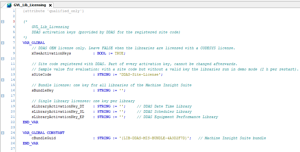
The image above shows the licensing part of the application template.
MergeLibFBErrors
General Information
This chapter describes the function block MergeLibFBErrors.
Function Block Name: MergeLibFBErrors
Location: Application Template, folder 09_ErrorFB
Dependent Codesys libraries: none
CODESYS Version Compatibility: CODESYS V3.5 and higher
License / Usage Restrictions: none (part of the Application Template)
Purpose & Scope
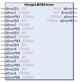
MergeLibFBErrors merges the error outputs of up to six function blocks into one error output, based on the priority order of its inputs.
It is delivered as source code in the Application Template and can be copied into any application.
Typical Use Case
Aggregating error outputs from multiple sub-function blocks.
Simplifying HMI/SCADA diagnostics.
Providing a single, clear fault message to operators.
Reducing complexity in higher-level control logic.
Advantages
Centralized error handling
Deterministic priority resolution
Improved readability and diagnostics
Scalable: several instances can be cascaded for more than six error sources
Functional Overview
The FB MergeLibFBErrors consolidates error outputs from up to six different function blocks into a single unified error output. It prioritizes errors based on a defined priority order (Priority 1 = highest, Priority 6 = lowest).
Key Functionality
Evaluates six independent error sources.
Applies a fixed priority scheme (1 → 6).
Outputs only the highest-priority active error.
Provides consolidated diagnostic information:
Error state
Error ID
Error message
Originating function block
Inputs
Each error source includes:
iErrorIDx (INT): Error/status identifier
sErrorx (STRING): Error description
sErrorFBx (STRING): Source function block name
Where:
x = 1...6
Priority is determined by index:
1 = Highest priority
6 = Lowest priority
Outputs
xError (BOOL)
TRUE if any error or warning is presentiErrorID (INT)
Error ID of the highest-priority active errorsError (STRING)
Error message of the selected errorsErrorFB (STRING)
Function block where the error originated
Behaviour
The function block scans inputs in ascending priority order (1 → 6).
The first detected valid error is selected.
All lower-priority errors are ignored once a higher-priority error is found.
If no errors are present:
xError = FALSE
Other outputs typically remain default/empty.
Interface Description
Function block Inputs and Outputs
| Scope | Name | Type | Comment |
|---|---|---|---|
| Input | iErrorID1 | INT | Error and status identifier Prio 1 |
| sError1 | STRING | sError string | |
| sErrorFB1 | STRING | sError Function block | |
| iErrorID2 | INT | Error and status identifier Prio 2 | |
| sError2 | STRING | sError string | |
| sErrorFB2 | STRING | sError Function block | |
| iErrorID3 | INT | Error and status identifier Prio 3 | |
| sError3 | STRING | sError string | |
| sErrorFB3 | STRING | sError Function block | |
| iErrorID4 | INT | Error and status identifier Prio 4 | |
| sError4 | STRING | sError string | |
| sErrorFB4 | STRING | sError Function block | |
| iErrorID5 | INT | Error and status identifier Prio 5 | |
| sError5 | STRING | sError string | |
| sErrorFB5 | STRING | sError Function block | |
| iErrorID6 | INT | Error and status identifier Prio 6 | |
| sError6 | STRING | sError string | |
| sErrorFB6 | STRING | sError Function block | |
| Output | xError | BOOL | TRUE if an error or warning is detected. Detailed error information is provided in iErrorID |
| iErrorID | INT | Error and status identifier for diagnostics | |
| sError | STRING | Error string | |
| sErrorFB | STRING | sError Function block |
Execution & Timing Behaviour
The function block is intended to be executed cyclically in a task context.
Timing precision depends on the configured task cycle time and target platform
Error Handling & Diagnostics
MergeLibFBErrors reports no errors of its own. The error codes and texts at its outputs are those of the source function blocks; use the Get_sError function of the respective library for the error text.
Assumptions & Limitations
Up to six error sources per instance; cascade several instances for more sources. An error ID of 0 means “no error”; warnings must use an ID other than 0 to be reported.
Example Implementation
The Application Template uses MergeLibFBErrors on two levels:
1. Per library: the errors of the library function blocks are merged into GVL_Par_xx (for example in prgScheduler, action act_03_Errorhandling). In prgEquipmentPerformance these are the errors of fb_EP, fb_EP_History and fb_EP_Result.
2. For the application: the licensing error and the errors of the three libraries are merged into the machine interface GVL_MIF (prgEquipmentPerformance, action act_03_Errorhandling):
| Priority | Error source |
| 1 | prgLicenseStatus (licensing) |
| 2 | GVL_Par_DT (Date Time Library) |
| 3 | GVL_Par_SL (Scheduler Library) |
| 4 | GVL_Par_EP (Equipment Performance Library) |
Declaration and Call of the Function Block MergeLibFBErrors:
VAR
fb_MergeLibFBErrors: MergeLibFBErrors;
END_VAR
FB call in structure text:
fb_MergeLibFBErrors(
iErrorID1 := fb_GetBuildTime.iErrorID,
sError1:= DDAS_SL.Get_sError(fb_GetBuildTime.iErrorID),
sErrorFB1 := 'fb_GetBuildTime',
iErrorID2 := fb_GetBatchEndTime.iErrorID,
sError2:= DDAS_SL.Get_sError(fb_GetBatchEndTime.iErrorID),
sErrorFB2 := 'fb_GetBatchEndTime',
iErrorID3 := fb_UpdateInterval.iErrorID,
sError3:= DDAS_SL.Get_sError(fb_UpdateInterval.iErrorID),
sErrorFB3 := 'fb_UpdateInterval',
iErrorID4 := fb_GetSchedule.iErrorID,
sError4:= DDAS_SL.Get_sError(fb_GetSchedule.iErrorID),
sErrorFB4 := 'fb_GetSchedule',
iErrorID5 := 0,
sError5:= '',
sErrorFB5 := '',
iErrorID6 := 0,
sError6:= ‘’,
sErrorFB6 := ‘’
);
FB call in continuous function chart diagram:
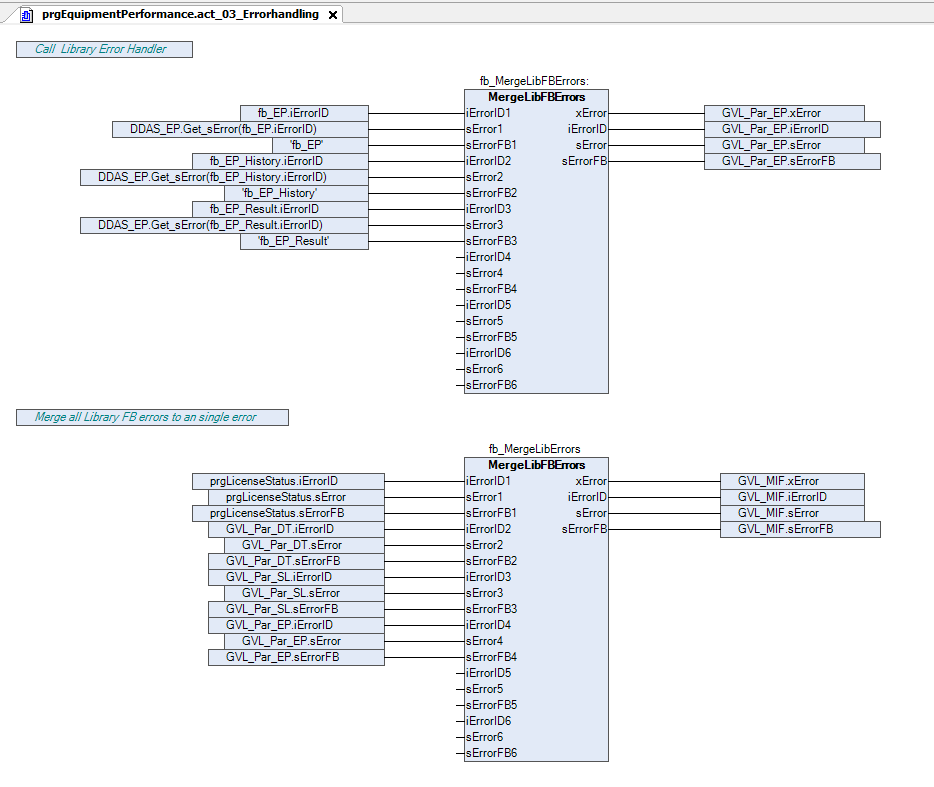
The image above shows the sample call auf the FB MergeLibFBErrors.
Your Feedback Matters
These instructions have been prepared to the best of our knowledge and belief to provide you with the highest possible level of support when working with our product.
Despite our best efforts, we may not always fully achieve this objective. If you identify any issues or have suggestions for improvement, we would greatly appreciate your feedback.
Please send your comments or criticism in a short e‑mail to:
Thank you for your support.
Your DDAS Application Software Team